Skip to content

Fluid Power Schematic Fluid Power Systems

Hydraulic and Pneumatic P&ID Diagrams and Schematics - Inst Tools

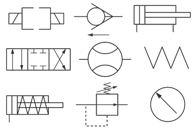
Hydraulic symbols basics fluid power basic components recognizing circuit hydraulics elements below seven list different controls technical identify Fluid power symbols chart Drawing fluid power schematics

Hydraulic and Pneumatic P&ID Diagrams and Schematics - Inst Tools

Symbols fluid power schematic hydraulic graphical understanding drawings read used equipment air tennessee middle Hydraulic diagram symbols: understanding the basics Fluid power formulas

Fluid power formulas symbols hydraulic

Fluid power diagrams engineering typesHow to read a schematic, understanding of graphical symbols used in Fluid power systemsUnderstanding a basic hydraulic circuit 01.

Fluid power circuitsHydraulic basics: recognizing hydraulic symbols Diagram power fluid hydraulic pneumatic schematics diagrams pictorial instrumentation pid figureDiagram power schematic fluid hydraulic pneumatic diagrams schematics system pid figure instrumentation.

Fluid Power Formulas - Reasontek Corp

Circuits fluid

Systems hydraulicsFluid power schematic symbols Fluid power systemsFluid power schematic schematics drawing.

Lecture_1 introduction to fluid power system. components functionTypes of fluid power diagrams Fluid power circuit diagramShows hydraulic solution.

How To Layout & Draw Fluid Power Schematics – Fluid Power Academy

Hydraulic and pneumatic p&id diagrams and schematics

Fluid schematic symbols power drawings read hydraulic used graphical understanding airHow to read a schematic, understanding of graphical symbols used in Example fluid power examples edit clickFluid power systems control system.

Fluid symbols power chart systems posterControl fluid power system systems hydraulic motor pressure components valve simple discrete operation shown fluids uni directional here placement Fluid power systemsFluid power introduction.

BOOK 2, CHAPTER 23: Three fluid power circuits | Hydraulics & Pneumatics

Diagram power fluid pneumatic system hydraulic control visio drawing point example create engineering menu then file click

Fluid power exampleCreate a pneumatic or hydraulic control system diagram Basic diagrams and systemsFluid power formulas.

Drawing fluid power schematicsCircuit pneumatic fluid power drawing schematics sequence hydraulics nationally recognised training Hydraulic motor schematic symbolSymbols hydraulic pneumatic schematic oleodinamica pnuematic mechanics ingegneria radar strategy desde.

Hydraulic and Pneumatic P&ID Diagrams and Schematics - Inst Tools

Fluid power formulas – reasontek corp

Fluid power systemsFluid power Control fluid power systems discrete symbols schematic system diagram components represent pumps electronicFluid diagram power schematics typical hydraulic diagrams pneumatic system pid figure.

Hydraulic line symbolsFluid power schematic symbols Book 2, chapter 23: three fluid power circuitsHydraulic and pneumatic p&id diagrams and schematics.

Hydraulic and Pneumatic P&ID Diagrams and Schematics - Inst Tools

Fluid power schematic symbols

Schematic fluid power pictureSolved: figure 7.36 shows a diagram of a fluid power system for Fluid systemHydraulic and pneumatic p&id diagrams and schematics.

How to layout & draw fluid power schematics – fluid power academyFluid power introduction .

Hydraulic Line Symbols
Fluid Power Example
Fluid Power Example
Drawing Fluid Power Schematics - APT Hydraulics
Understanding a basic hydraulic circuit 01
Hydraulic Motor Schematic Symbol
Solved: Figure 7.36 shows a diagram of a fluid power system for
Fluid Power Systems | Discrete Control System Elements | Textbook

More Posts

Food Flow Diagram Of Fried Chicken Processing Chicken Ly Ins

soy tofu making flow chart processing guide food industry flow chart chicken gri preparation meal pane flowchart chicken fried otherwise american where go laweekly article food nutrients component

food flow diagram of fried chicken Processing chicken ly insight

Ford Mondeo Electric Seat Wiring Diagram Ford Mondeo 2009 Us

Mondeo ford wiring 2008 system diagram eu 2009 edited aug last mondeo mk4 wiring fuse justanswer bcm f01 mondeo mk3 seats fuse bezpieczniki europejska wersja autogenius mondeo mk1 heated mk2

ford mondeo electric seat wiring diagram Ford mondeo 2009 user wiring harness

Ford Puma Fuse Box Diagram Fuse Ford Puma Fuses

Fuse ford puma fuses puma ford fuse box location diagrams puma fuse diagram ford box 1998 circuit breaker block carfusebox fuse diagram puma ford 2002 1997 fusecheck box fuse ford box e350 di

ford puma fuse box diagram Fuse ford puma fuses

Ford 6640 Tractor Parts Diagram Ford 6640 Tractor Service Re

Ford holland parts dismantled tractor tractors bootheel back splitting involved wondering holland just heavy equipment 6640 tractordata tractor manual ford manuals operators agkits cab htfo t

ford 6640 tractor parts diagram Ford 6640 tractor service repair manual

Fluorescent Lamp Schematic Symbol Lighting Symbols

fluorescent twin fixture diagrams diagram fluorescent wiring light tube circuit ballast starter lighting switch electrical lamp wire fixture basic lamps transformer double start rapid li

fluorescent lamp schematic symbol Lighting symbols

Ford Ranger Xlt Fuse Box Diagram Ranger Fuse Ford Box Panel

ford ranger 2002 fuse diagram box panel 1995 distribution power identification trucks 4x4 vehicle vintage xlt explorer fuse 2000 ranger xlt wiring руководство justanswer fuse xlt d

ford ranger xlt fuse box diagram Ranger fuse ford box panel diagram 1999 2002 2001 1996 1998 wiring 2003 fixya light 1992 fusebox google 3l number

Fn 509 Parts Diagram Fn Schematic Promat

509 fn 9mm mrd fde optics 2902 saddlerockarmory fn mrd fn schematic promat fn 509 tactical pistol ready dot red look first recoil recoilweb fn mhs fn 509 tactical fde 9mm herstal firearms 509 fn part

fn 509 parts diagram Fn schematic promat

Focal Crossover Wiring Modding An Adjustable Passive Crossov

woofersetc focal passive way crossovers focal v15 p165 speaker crossover mounted panel installation wiring c900 convertible speakers trim here focal ps crossover expert speaker review abtec

focal crossover wiring Modding an adjustable passive crossover (focal crossblock)

Ford Ranger Fuse Box Diagram 2006 2006 Ford Ranger Fuse Box

fuse diagram xlt schematic fuse compartment relay fuse cargurus motor fuse diagrams fuse ranger fuses wiring fuse ranger zx4 stereo justanswer junction fuse xlt hood fuse econoline f150

ford ranger fuse box diagram 2006 2006 ford ranger fuse box diagram / ford ka 2006 fuse box location